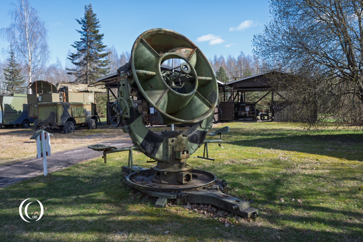
The Ringtrichter-Richtungshörer (RRH) was a specialized circular acoustic locator developed in Germany during the 1930s. Designed to provide an early warning system against aerial threats for the German Army, it represented a unique approach to sound-based detection.
Design and Development
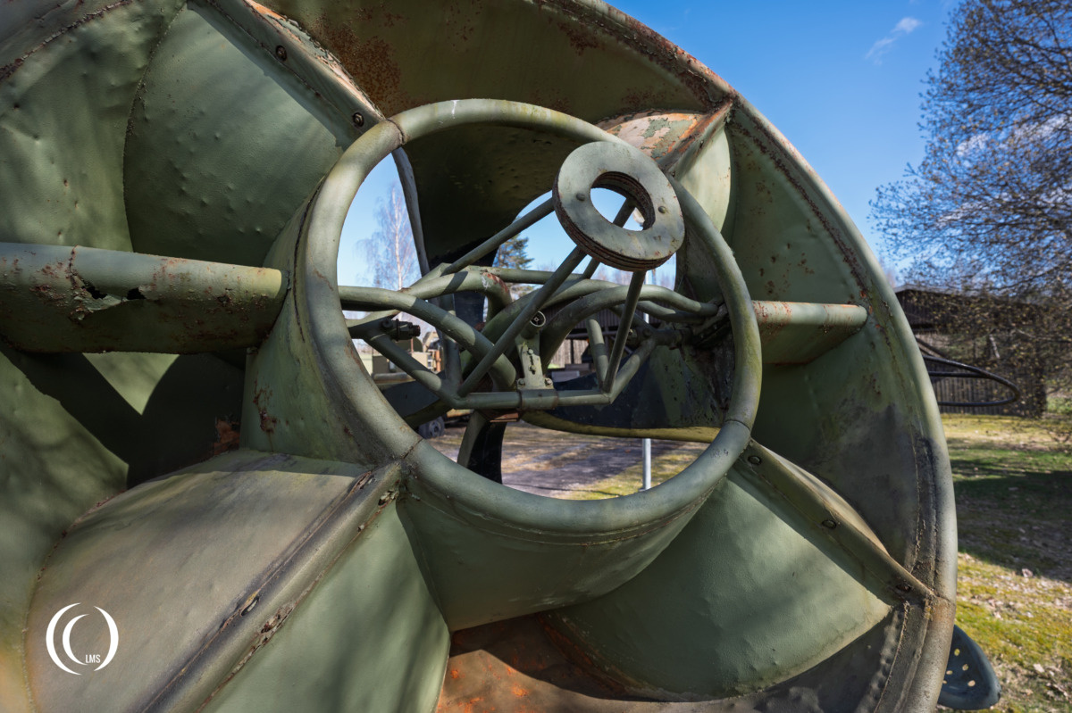
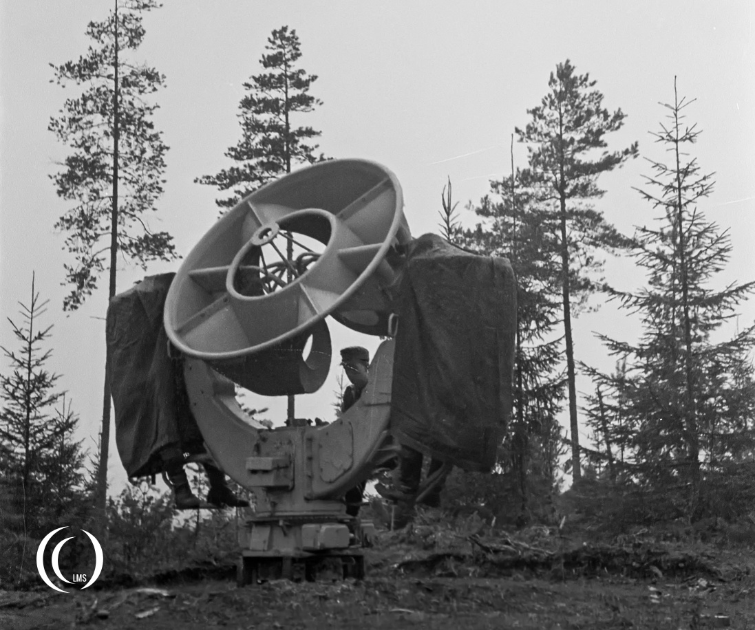
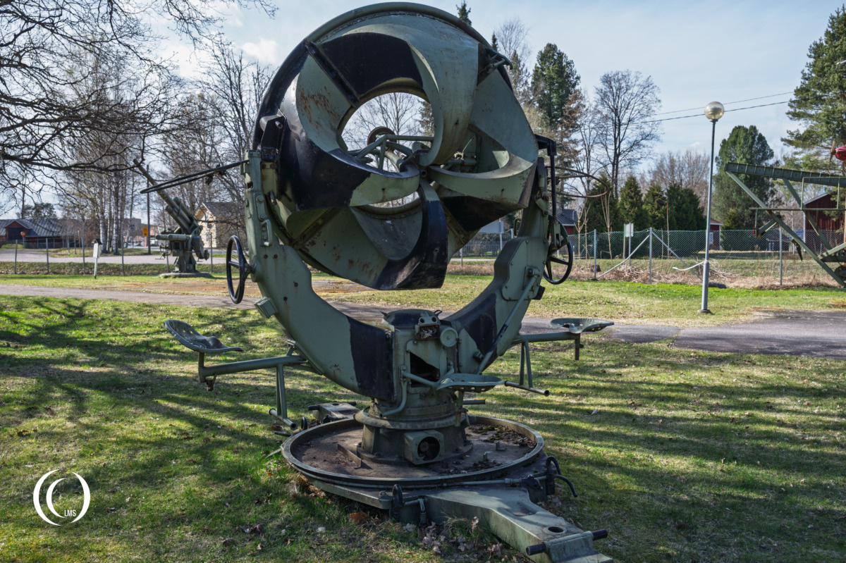
The innovation of the RRH device lay in its circular horn arrangement. Unlike traditional, single-horn acoustic locators, the RRH utilized a ring of horns designed to work in conjunction with stereo headphones. The latter were connected to acoustic tubes rather than electronic amplification. This configuration allowed operators to achieve much more precise sound localization of approaching aircraft by providing a clear sense of direction through stereo audio. When multiple units were operating in coordination, they could perform rudimentary triangulation to pinpoint the exact position of an incoming aircraft.
Technical details
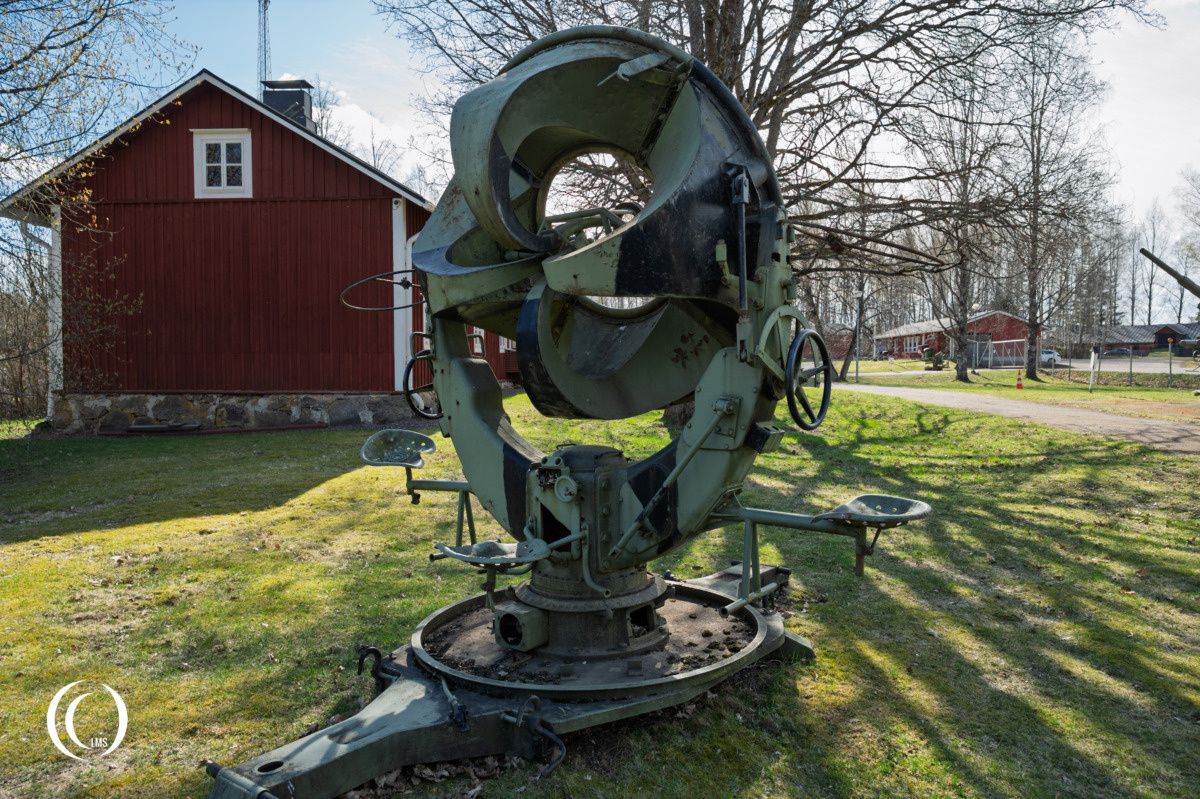
The Ringtrichter-Richtungshorer (RRH) consisted of the following parts:
Bed (Base frame)
Serving as the device carrier consisting of a base plate with 4 adjustment spindles and a bed support with a hook for lifting chains, opening for centering pins, 2 bearing pins, and light connection ports, and a tube-shell. The bed also included a control set for the lower part (with socket) and a collector- and signal box.
Pedestal
Steel construction carrying the column with the two support arms and the ring-funnel.
Column
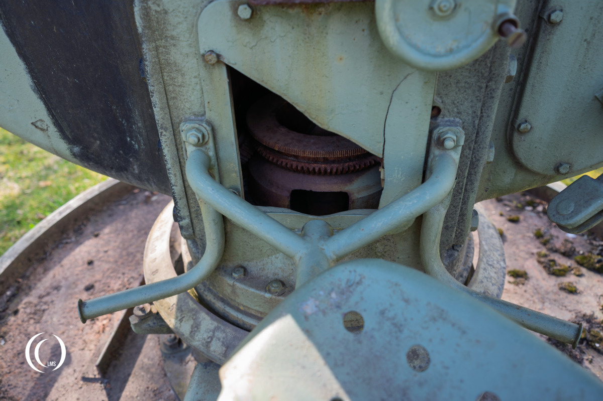
A right-angled steel body serving as the housing of the delay calculator and carrying the entire device, except for the three operators. The main bearing allowed for easy rotation of the device.
Support arms
Supporting the ring-funnel (ringtrichter).
Ring-funnel
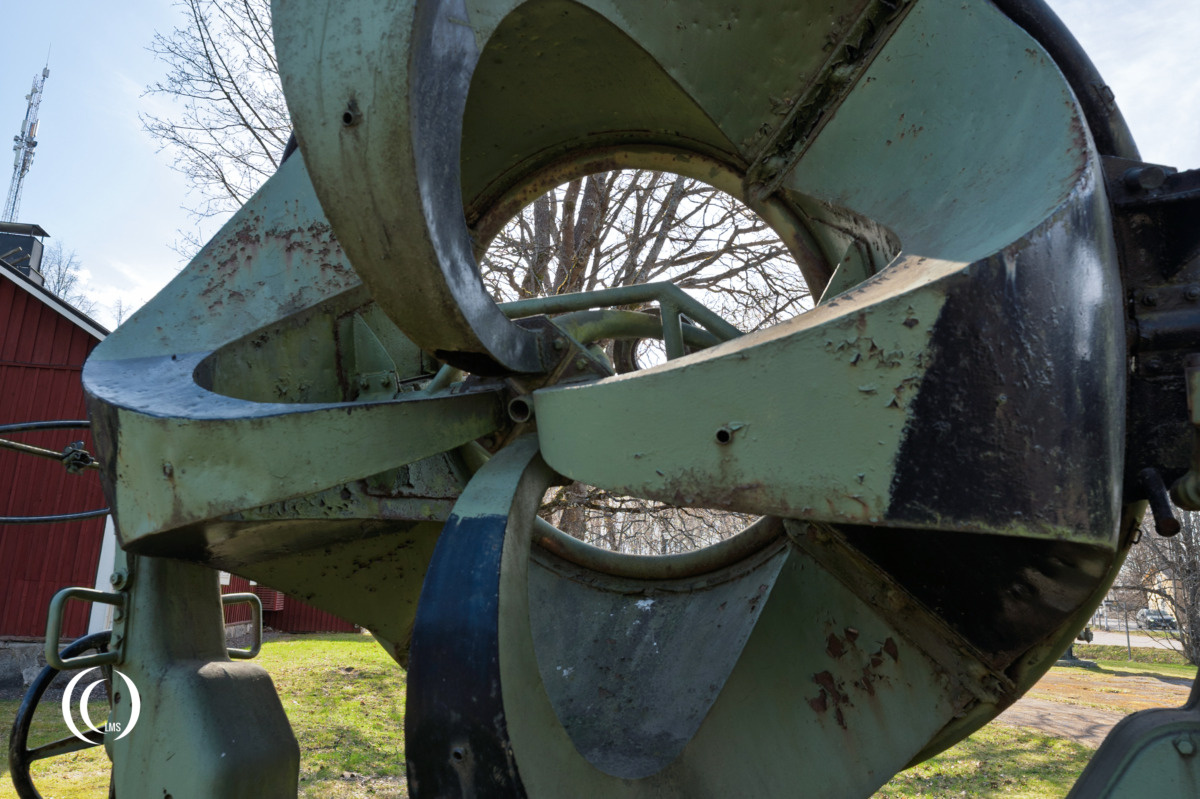
4 funnels joined together by the outer, inner, and holding rings. All edges were rounded to prevent wind noise. The two lateral funnels were for determining the lateral direction, and the vertical ones are for elevation.
Elevation adjustment
The elevation of the ring-funnel could be adjusted by a lead screw and a hollow shaft with a transmission ratio of 8:1. The hollow shaft was connected to the elevation degree arc via a push rod and also connected to the ring-funnel’s funnel-ring via a push rod, ensuring that values are transferred angularly (elevation angle – parallelogram). For precise adjustment, the push rod had a screw thread.
Lateral direction adjustment
The lateral direction of the device was adjusted by the side handwheel. Transmission was via a gear pair, the split shaft (which compensates for temperature changes), and the winding mechanism. The small gear engaged with the upper part of the pedestal and rotated the column with the support arms on the pedestal. The transmission ratio of the handwheel to the pedestal was also 8:1, i.e., rotating the handwheel eight times rotated the device once.
Delay calculator
The RRH had its own delay calculator integrated in the device column. It continuously calculated the triangle (flight path) lying in space, which was formed by the acoustic and optical directions and the flight path of the aircraft. The sound delay time had to account for deviations between the two directions; this deviation was automatically canceled in the pre-set of the delay calculator.
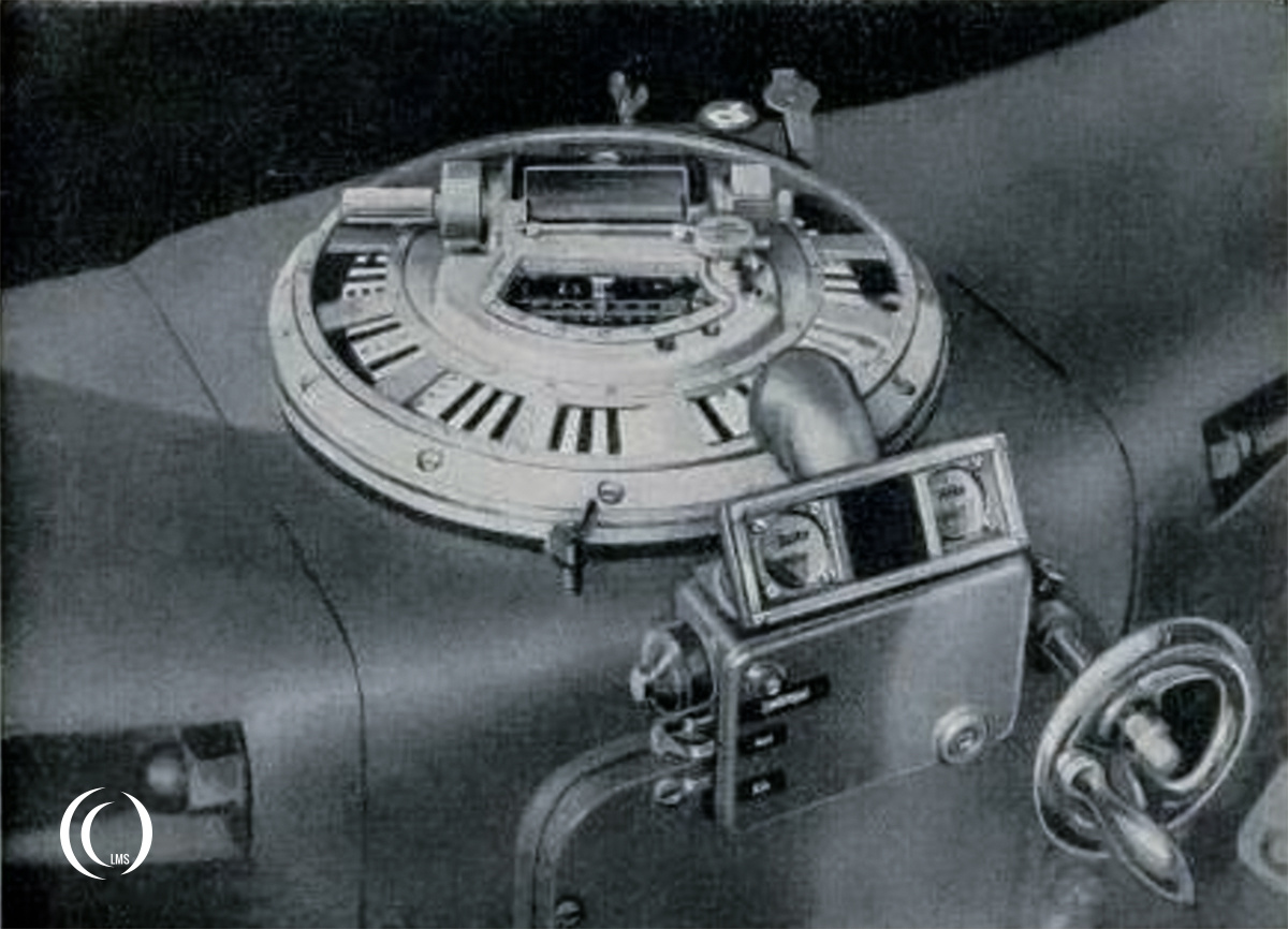
Transmission mechanism
The transmission mechanism passed the elevation and lateral angles (the indicators glowing on the RRH) to the anti-aircraft searchlight.
Light and signal system
The light and signal system that was required for the operation of the device and the understanding of the listeners.
The light system consisted of a:
- Lamp on the elevation degree arc (yellow pointer)
- Lamp on the right support arm’s elevation degree arc
- Lamp on the lateral circle (white and yellow pointer)
- Lamp for the delay calculator’s display plate
- Hand lamp (connection to collector)
The signal system consisted of three signal boxes, namely:
- Signal box for elevation — on the right support arm.
- Signal box for lateral direction — on the left support arm.
- Signal box for the delay calculator — on the column.
Through a manual contact, the listeners could report their respective “central impression” to the delay calculator operator by lighting up the sign “Elevation heard” or “Lateral heard” in all signal boxes. When both signals lit up, the delay calculator, by pressing a button, sent the position to the anti-aircraft searchlight.
Accessories
The RRH device came with the following accessories:
- The cover
- 2 rings for the rain tents
- 2 rain tents
- 2 headsets, both with 2 listening tubes and 2 ear shells
- 3 manual contacts with lead-in cables (one as a spare)
- 2 cover plates for 36-pin socket parts as spares
- 1 hand lamp
Underneath two illustrations of the Ringtrichter-Richtungshorer (RRH) – Governing regulation document: L. Dv. 604 (Abb. 118 and 118).
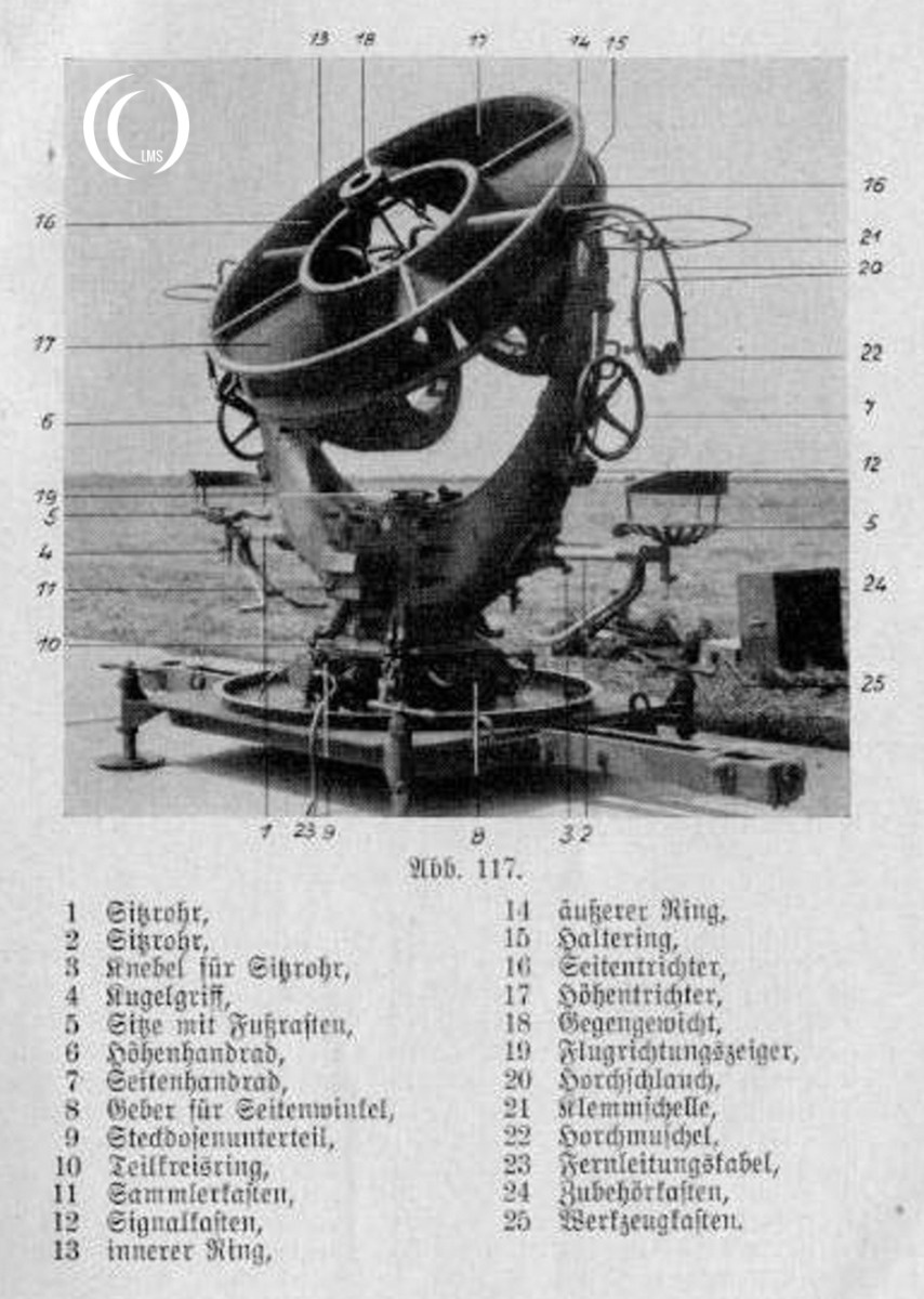
Image (Abb.) 117 translated components explanation:
- Siebrohr: Sight tube / Sighting tube
- Siebrohr: Sight tube / Sighting tube
- Knebel für Siebrohr: Knob for sight tube
- Kugelgriff: Ball grip / Spherical handle
- Sitz mit Fußrasten: Seat with footrests
- Handgriff: Handgrip / Handle
- Seitenhandrad: Side handwheel
- Geber für Seitenwinkel: Lateral angle transmitter / generator
- Steuersatzunterteil: Control unit lower part / Base of control set
- Teilkreisring: Partial circle ring
- Sammelkasten: Collector box / Junction box
- Signalkasten: Signal box
- Innerer Ring: Inner ring
- Äußerer Ring: Outer ring
- Haltering: Holding ring / Retaining ring
- Seitentrichter: Side horn / Lateral funnel
- Höhentrichter: Elevation horn / Height funnel
- Gegengewicht: Counterweight
- Flugrichtungszeiger: Flight direction indicator
- Hörschlauch: Listening tube / Ear tube
- Klemmleiste: Terminal strip / Clamp strip
- Hörschläuche: Listening tubes (Likely, based on the context of item 20)
- Fernleitungskabel: Remote line cable
- Zubehörkasten: Accessory box
- Werkzeugkasten: Toolbox
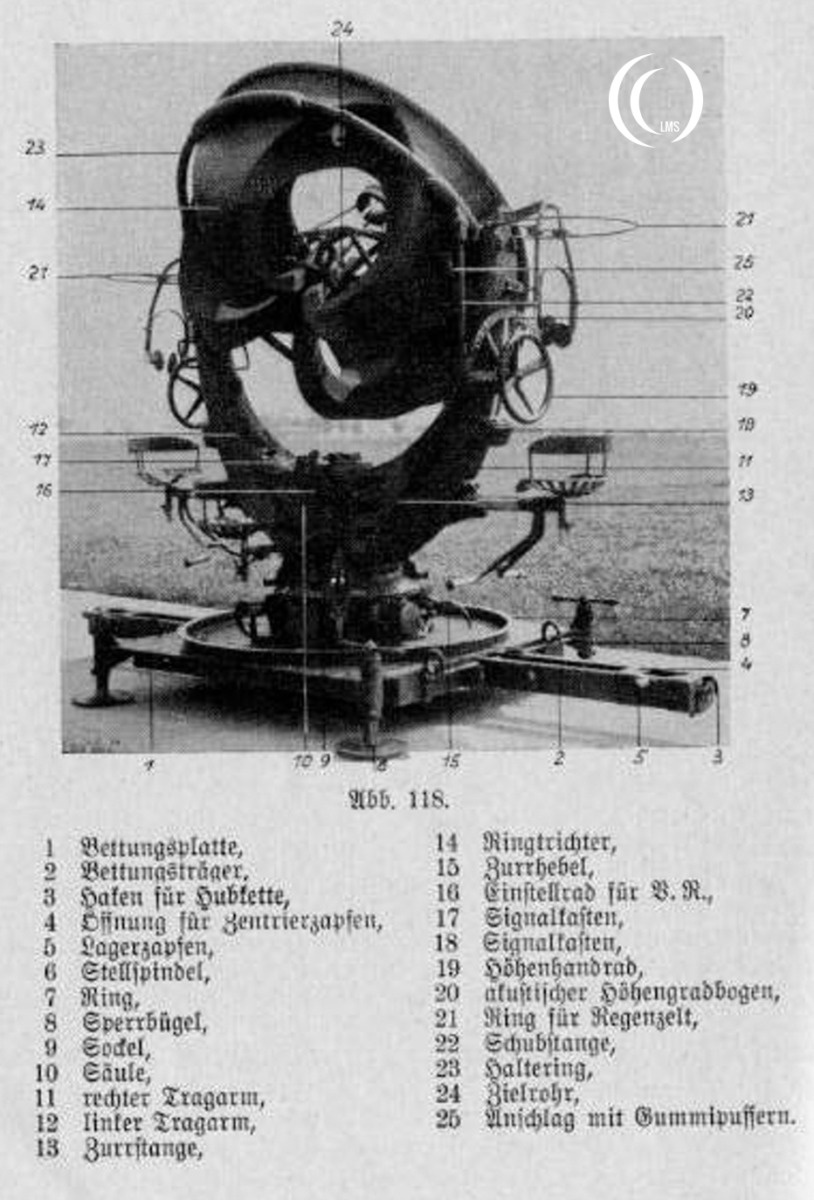
Image (Abb.) 118 translated components explanation:
- Bettungsplatte: Bedding plate / Base plate
- Bettungsträger: Bedding support
- Haken für Hubkette: Hook for lifting chain
- Öffnung für Zentrierzapfen: Opening for centering pin
- Lagerzapfen: Bearing pin / Pivot pin
- Stellspindel: Adjustment spindle / Screw jack
- Ring: Ring
- Sperrbügel: Locking bracket / Locking loop
- Sockel: Base / Pedestal
- Säule: Column
- rechter Tragarm: Right support arm
- linker Tragarm: Left support arm
- Zurrgatte: Lashing / Tie-down component
- Ringtrichter: Ring horn / Ring funnel
- Zurrhebel: Lashing lever (Note: The text in the image appears to be “Zurrhebel”)
- Einstellrad für B. R.: Adjustment wheel for B.R. (technical abbreviation)
- Signalkasten: Signal box
- Signalkasten: Signal box
- Handrad: Handwheel
- Aufrichte Höhengradbogen: Elevation degree arc (Leveling/erecting arc)
- Ring für Regenzelt: Ring for rain tent / canopy ring
- Schubstange: Push rod / Thrust rod
- Haltering: Retaining ring / Holding ring
- Zielrohr: Sight tube / Aiming tube
- Anschlag mit Gummipuffern: Stopper with rubber buffers
Production and Distribution
Manufacturing began in Germany in the 1930s, with thousands of units being produced over the following decade. The technology was also exported to Finland and other nations friendly to Germany at the time. Various specialized models were continuously developed to improve accuracy, with production continuing through 1944. By the height of the war, German air defenses utilized approximately 5,500 units of various RRH models.
Operation
Operation required a listening team consisting of a team leader, an operator for the delay computer on the back of the device and two specialized listeners: one assigned to the vertical axis and one to the horizontal axis. To locate an incoming aircraft, operators would swing the device’s ring-funnels to find a “central impression”; a state where the engine noise reaches both ears simultaneously without any time difference. Once this was achieved, the operators would independently press a hand button to signal they had centered the target.

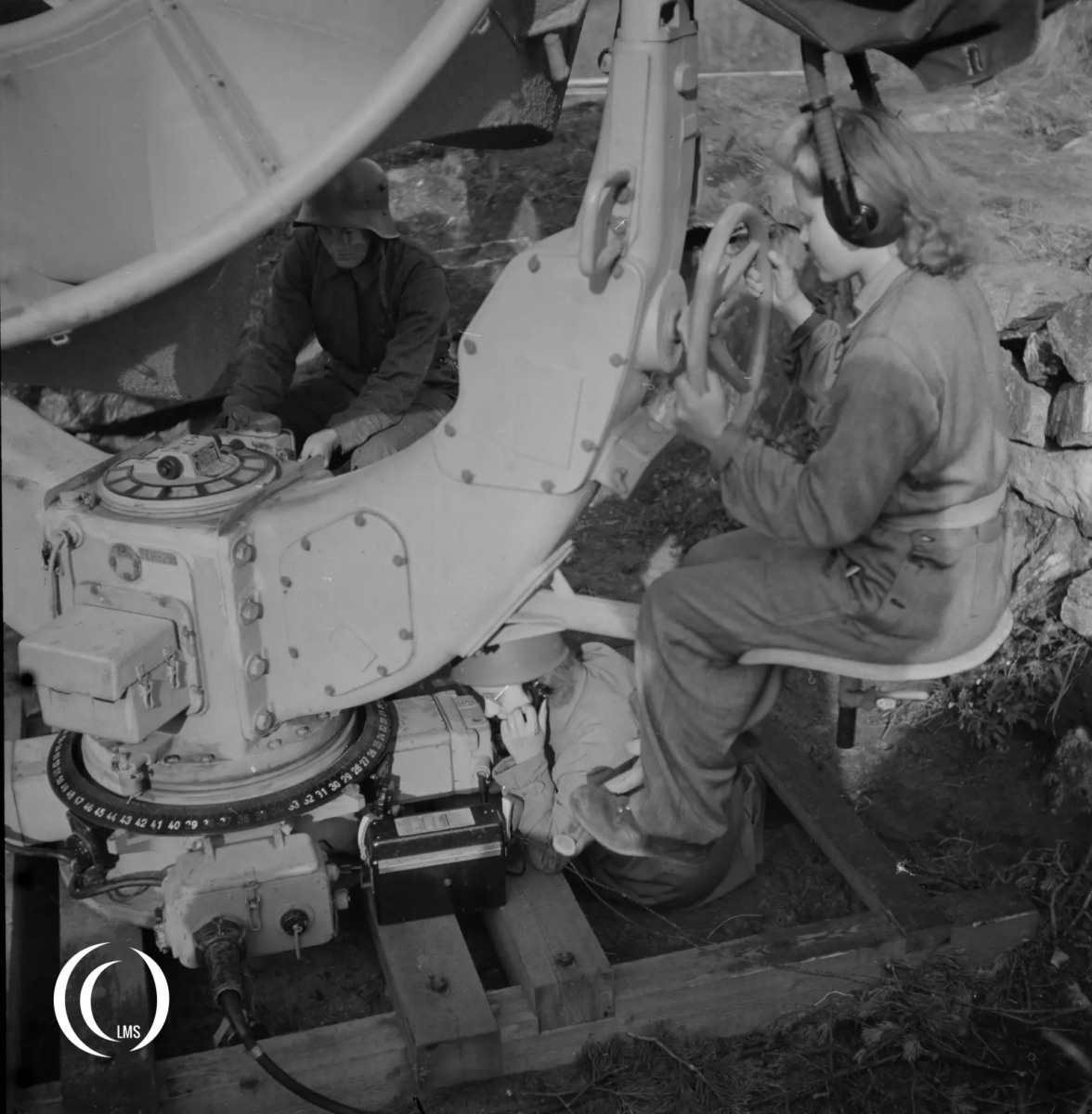
Once the buttons were pressed, a delay calculator located on the back of the device would process the information. By accounting for the target’s movement and an estimated speed, the calculator determined the distance the aircraft had covered on the ground. These calculated angular values were then transmitted to anti-aircraft searchlights via telephone or electronic means, providing the necessary guidance to help their crews locate and acquire the target.
Use in WWII
During World War II, the RRH served as a vital component of ground-based air defense. Its primary purpose was to detect incoming aircraft before they reached the engagement range of anti-aircraft guns or searchlights. In optimal weather conditions, a coordinated group of RRH units could detect approaching targets at ranges as great as 12 kilometers. This early warning capability provided defenders with critical time to prepare.

While the advent of radar, like the Würzburg FuMG/FuSE, rendered acoustic locators obsolete early in World War Two, the RRH remained a significant tool during the war. The reason for this was that the supply of these radar systems was just enough to equip the anti-aircraft batteries. And so listening-devices, although limited to a role of guiding searchlights, remained in use until the end of World War Two.
In Finland, where the devices had been used for air-defense, they were eventually phased out in the early 1950s.
Surviving Ringtrichter-Richtungshorer (RRH)
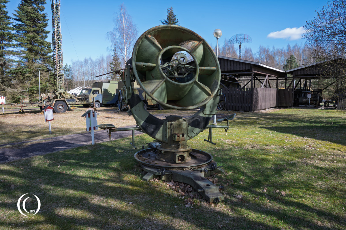
The Ringtrichter-Richtungshorer (RRH) device in the pictures was photographed at the Anti-Aircraft Museum in Tuusula, Finland.
Sources
- Anti-Aircraft Museum documentation
- Wikipedia.org
- festungswerke-cuxhaven.de
- sa-kuva.fi
- Luftwaffe-Dienstvorschrift 604 manual (L. Dv. 604)
